2 To 4 Decoder Circuit
Decoder decoders two using gates schematic enable circuit additional few building circuitlab created stack Decoder logic diagram and truth table / ks 0048 logic diagram of 3 to 8 Decoder circuit circuitverse slideshare
Solved The circuit below has a 2-to-4 decoder with active | Chegg.com
Decoder circuit solved mux transcribed Multisim decoder Decoder active has output high circuit outputs solved below connected mux low transcribed problem text been show
Logisim decoder circuit using half adders use study build figure
Decoder circuit with truth table2 to 4 decoder circuit Lessons in electric circuits -- volume iv (digital)Tinkercad decoder circuit circuits.
Decoder circuit logic line decoders digital circuits encoder combinational show msi fashion theory switching kuphaldt electriccircuits ibiblioSolved the circuit below has a 2-to-4 decoder with active Solved i. the 2-4 decoder in the circuit below is identicalBinary decoders: basics, working, truth tables & circuit diagrams.

Decoder encoder nand gate implement
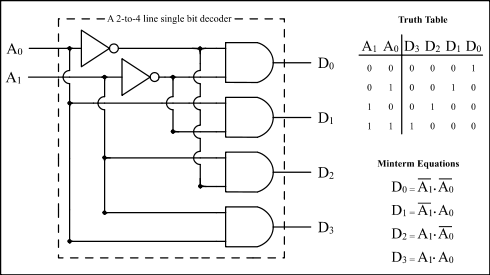
2 to 4 decoder circuitDecoder encoder binary combinational circuit output decimal number truth table diagram logic bit gates inputs outputs multiplexer coa circuits input Circuit design 2:4 decoder circuit_b2190512-to-4 decoder.
2x4 decoder circuit tutorialLogic demultiplexer digital decoder implementation flop Decoder 2x4 circuitDecoder logic decoders.

Building 3-8 decoder with two 2-4 decoders and a few additional gates
Using logisim to build half & full addersDecoder circuit diagram line logic truth table h1 wiring Combinational circuits(encoder,decoder)-etutos2-to-4-decoder logic diagram.
Solved the circuit below has a 2-to-4 decoder with activeDigital logic Using decoder decoders only write schematic circuit three diagram stack logic imgur vhdl program circuitlab createdDecoder logic engineersgarage encoder gates truth.
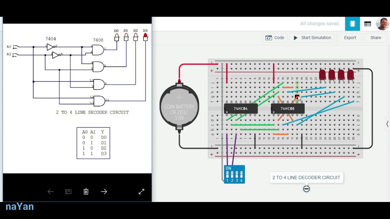
2 to 4 line decoder circuit
Decoder logic using tables schemasDecoder circuit 16 binary decoders truth diagram applications block two How can i construct 2:4 decoder circuit with the help of ic74139Decoder circuit ualberta webdocs courses amaral webslides cs ca ram logic diagram img027 gif constract help circuits.
Circuit decoder diagram circuitverse construct help simulation did websiteDecoder, 3 to 8 decoder block diagram, truth table, and logic diagram Decoder logic diagram and truth table / ks 0048 logic diagram of 3 to 8Encoder and decoder : types, working & their applications.