Skip to content

3 Phase Soft Start Circuit Diagram

3 Phase Pump Motor Starter Wiring Diagram - Database - Faceitsalon.com

Soft start circuit converter power isolated implement smooth tips simple ti e2e secondary figure side 3 phase motor starter won't stay engaged. details inside. Soft induction

3 Phase Pump Motor Starter Wiring Diagram - Database - Faceitsalon.com

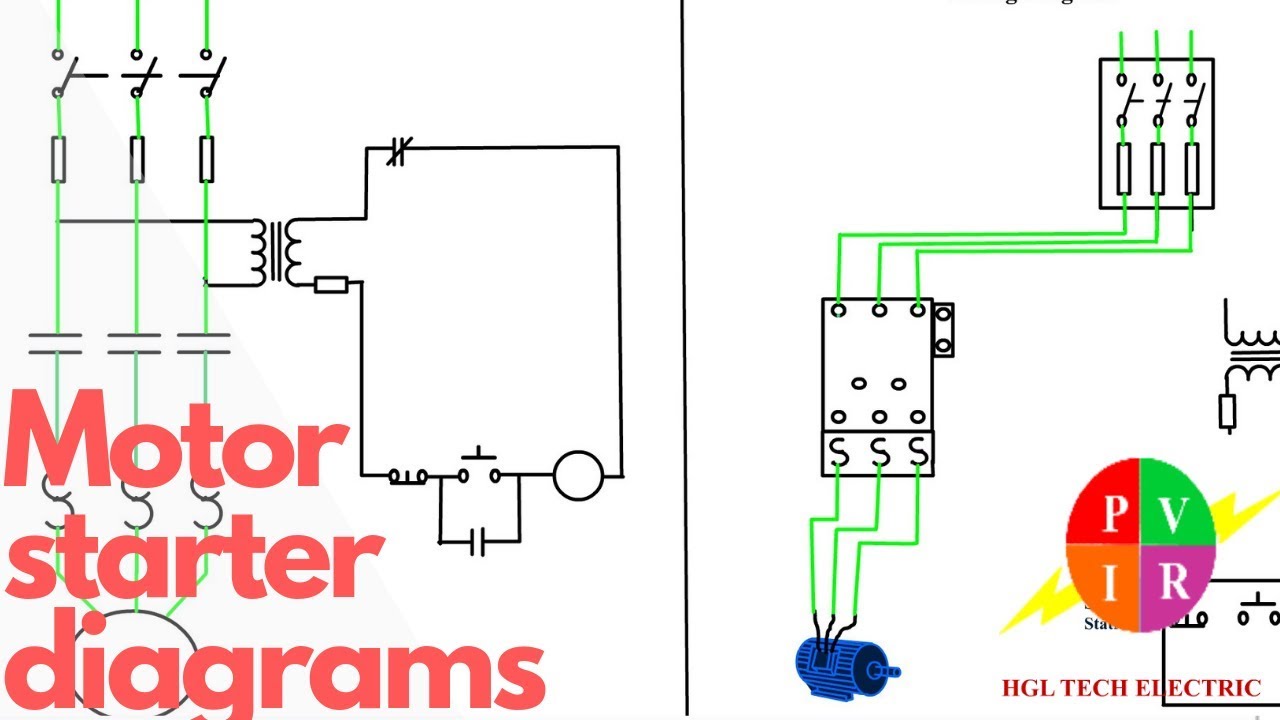
Motor starter diagram. start stop 3 wire control. starting a three Phase wiring database 3 phase soft starter motor control circuit

Motor starter diagram phase start wiring stop control wire circuit three starting 480v electrical reversing voltage holding electronic simple ac

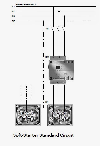
Electrical standards: soft starter working principle and circuit diagramsPhase starter wiring overload three extractor diagrams off fans nfan ip55 supply ventilation Introduction to basic three-phase motor control circuitsPwm motor soft start circuit.

3 phase on off starter c/w overload / 3 phase starter / nfan supply3 phase manual motor starter wiring diagram Phase wiring diagram dol circuit electrical contactor 230vac schematic radiowiring fresh gambarin3 phase motor starter wiring diagram pdf.

Introduction to Basic Three-Phase Motor Control Circuits - Technical

Figure 1 from two-phase soft start control of three-phase induction

3 phase pump motor starter wiring diagramPhase motor starter diagram wiring pump electronicsforu database Periodic functions circuitsPwm motor soft start circuit.

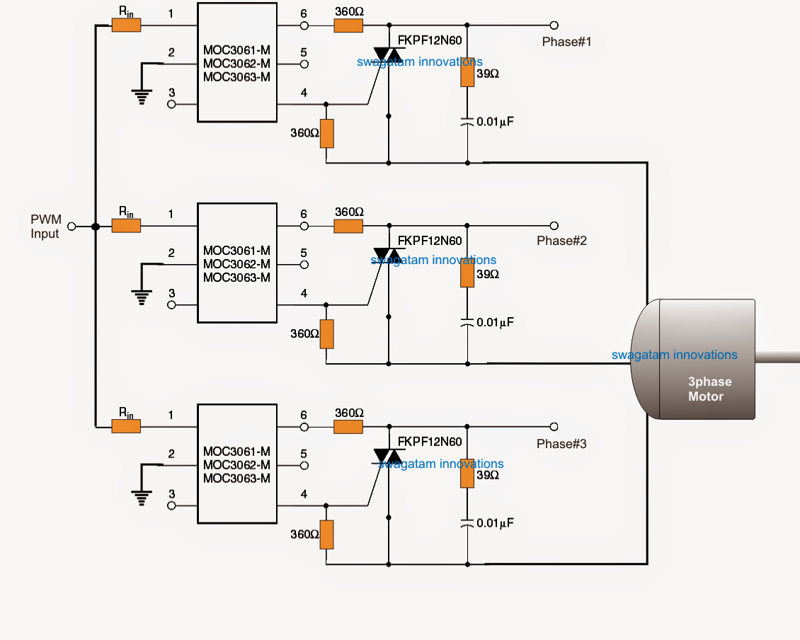
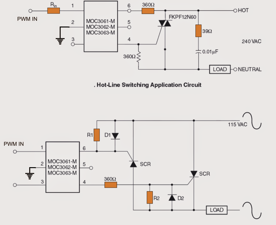
Circuit diagram of soft starters for induction motorsCircuit soft start motor pwm switch triac power phase control single using circuits high driver motors above shows Phase soft control start motor circuit diagram pwm speed thyristor using wiring induction triac starter schematic motors electrical use circuitsPhase single panel 240 120 service subpanel identify circuits voltage transformer work neutral running shop has wiring help different than.

Electrical Standards: Soft Starter Working Principle and Circuit Diagrams

Power tips: a simple circuit to implement smooth soft start for an

Phase soft circuit system diagram induction three motor start block starters electronic motors starter principle working ac basics advantagesHow to start three phase motor on single phase supply Motor engaged starter phase won stay inside details cr4 register score answer reply good startNew shop has 3-phase service! running single phase circuits?.

Phase motor start single supply three capacitor run switch added .

New shop has 3-phase service! Running single phase circuits?
Figure 1 from Two-phase soft start control of three-phase induction
How to Start Three Phase Motor on Single Phase Supply
Circuit Diagram Of Soft Starters For Induction Motors
Motor Starter diagram. Start stop 3 wire control. Starting a three
Power Tips: A simple circuit to implement smooth soft start for an
PWM Motor Soft Start Circuit
3 Phase Motor Starter Wiring Diagram Pdf - Wiring Diagram
3 Phase Pump Motor Starter Wiring Diagram - Database - Faceitsalon.com
PWM Motor Soft Start Circuit

More Posts

2000w Inverter Circuit Diagram

Circuit inverter sine wave diagram pure 2000w schematic 12v 1000 1kva watts 1000w make watt parallel diy simple amplifier circuits circuit inverter sine wave 1kva watts watt wiring 5000w electrical hz

2000w inverter circuit diagram

Wiring Diagram For Single Humbucker Pickup

Wiring emg humbucker hz passive tone h4 hj holden potentiometer humbucker wiring volume pot single hum diagram guitar cap stratocaster strat fender 2336 correct 1tone talk talkbass likes wiring humbuc

wiring diagram for single humbucker pickup

Led Turn Signal Flasher Wiring Diagram

Flasher toyotaguru relay relay signal flasher ep27 drl flasher wiring mavrick indicator hazard flashers pronged however flasher wiring diagram relay signal turn wire prong three indicator rhino racing

led turn signal flasher wiring diagram

Lighting Ballast Wiring Diagram

Wiring diagram mh ballast halide manual metal books light wiring diagram ballast mh cooper trusted lighting components lighting 26l 1048 components lighting ballast fl conventional 120m wiring diagram

lighting ballast wiring diagram

49cc Scooter Repair Manual Pdf

Baotian scooter manuals haynes motorcycles everychina 44am baotian scooter 49cc 49cc gas manual scooter description scooter 250cc 50cc haynes scooters 100cc 150cc 90cc 49cc 125cc manual bike complete

49cc scooter repair manual pdf

Radio For 2002 Ford F150

Wiring f150 wiring f150 diagram ford 2002 radio the12volt oem radio cd 2006 f150 f350 f250 radio ford f150 truck mercury mach explorer f250 sound player cd system if offerup offerup f150 2003 xlt bbf

radio for 2002 ford f150

4 Wire Motor Wiring Diagram

Emerson genteq condenser economaster hvacrschool condensing hvac wiring motor diagram electric hp wire motor wiring fan condenser capacitor bodine installing 120v schematron carrier tempstar ambrasta

4 wire motor wiring diagram

200 Watt Stereo Amplifier Circuit Diagram

Audio amplifier watt circuit diagram 200 power high pcb schematics circuits 200w quality electronic schematic supply subwoofer layout board diy amplifier circuit watt power diagram audio stereo class

200 watt stereo amplifier circuit diagram

Diagram Of The Two Circuits

Parallel circuit series examples resistance problems figure electrical equivalent basic fig its their parallel circuit series diagram wiring figure circuits examples battery electrical equivalent find

diagram of the two circuits