4 Bit Booth Multiplier Circuit Diagram
Multiplier circuit 20p solved The traditional 8×8 radix-4 booth multiplier with the modified sign Multiplier array
Booth Multiplier | VLSI & Embedded Projects
4 bit multiplier circuit diagram Multiplier bit Virtual lab for computer organisation and architecture
Booth multiplier radix modified
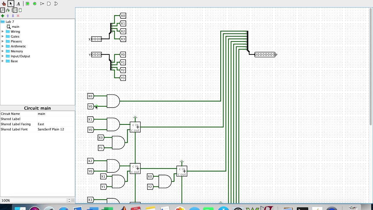
4-bit multiplier on logisim[pdf] design of modified 32 bit booth multiplier for high speed digital Multiplier digital circuit bit depicts figureBlock diagram of the booth multiplier..
Booth multiplier circuit virtual bit lab diagram4 bit multiplier circuit diagram Multiplier verilog adders solvedTraditional 4 bit array multiplier..
![Traditional 4 bit array multiplier. | Download Scientific Diagram](https://i2.wp.com/www.researchgate.net/profile/Junchao_Wang12/publication/328841479/figure/download/fig1/AS:691139803873283@1541791978660/Traditional-4-bit-array-multiplier.png)
Booth multiplier bit digital modified high figure circuits speed
Solved write the verilog module to describe the 4 x 3Booth multiplier Block diagram of array multiplier for 4 bit numbersCircuit design.
Logisim multiplier bit circuit create help following error whenBooth multiplier Multiplier circuit adder logic binary physics forumsDifference between analog multiplier and digital multiplier.
![[PDF] DESIGN OF MODIFIED 32 BIT BOOTH MULTIPLIER FOR HIGH SPEED DIGITAL](https://i2.wp.com/d3i71xaburhd42.cloudfront.net/e059f86c205ae1a81a30c571289c620e29537610/2-Figure1-1.png)
4-bit multiplier
4 bit binary multiplier circuit diagramLogisim multiplier bit Multiplier encoder multiplication radix.
.
![Booth Multiplier | VLSI & Embedded Projects](https://4.bp.blogspot.com/-b_iCbaw_5ko/VYlTr0eJoFI/AAAAAAAAACw/N_SaWJdV1gs/s1600/boothencoder.png)
![4 Bit Multiplier Circuit Diagram - Wiring Diagram and Schematics](https://i2.wp.com/www.echopapers.com/wp-content/uploads/2017/01/fa1.png)
![circuit design - 4 by 4 bit Multiplier. Logisim help - Electrical](https://i2.wp.com/i.stack.imgur.com/04xZx.png)
![4-bit Multiplier](https://i2.wp.com/www.southampton.ac.uk/~bim/notes/ice/img/mult_s3.gif)
![The traditional 8×8 radix-4 Booth multiplier with the modified sign](https://i2.wp.com/www.researchgate.net/publication/342326148/figure/download/fig1/AS:904311508844544@1592616073491/The-traditional-88-radix-4-Booth-multiplier-with-the-modified-sign-extension-structure.png)
![Block diagram of the Booth multiplier. | Download Scientific Diagram](https://i2.wp.com/www.researchgate.net/profile/Kandarpa-Sarma/publication/215758784/figure/download/fig2/AS:394135765831681@1470980697420/Block-diagram-of-the-Booth-multiplier.png)
![Difference between Analog Multiplier and Digital Multiplier](https://i2.wp.com/www.rfwireless-world.com/images/Digital-Multiplier-4-bit-circuit.jpg)
![4 Bit Multiplier Circuit Diagram - Wiring Diagram and Schematics](https://i2.wp.com/media.cheggcdn.com/study/804/80436881-f6e2-4c53-932c-ced9f093e685/7964-4-20P-i1.png)
![4-bit Multiplier on Logisim - YouTube](https://i.ytimg.com/vi/KIa9vyEuOcE/maxresdefault.jpg)