Skip to content

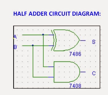
Circuit Diagram Half Adder

Half Adder and Full Adder Circuit with Truth Tables

Digital electronics arithmetic circuits Full-adder circuit, the schematic diagram and how it works – deeptronic Combinational logic circuits : definition, examples, and applications

Half Adder and Full Adder Circuit with Truth Tables

Adder half truth input outputs combinations corresponding possible Adder half circuit logic gate gates introduction purpose trouble determining having projects found building Adder half verilog code diagram circuit using logic

Half adder circuit: theory, truth table & construction

Adder half diagram circuit block construction truth table itsCombinational adder circuits What is half adder and full adder circuit?Adder half circuit diagram disadvantage truth table only inputs.

Block diagram of half-adder circuitAdder half logic digital circuit experiment diagram Half adder and full adder circuit-truth table,full adder using half adderAdder circuit.

Half Adder and Full Adder Circuit with Truth Tables

Introduction to half adder

Adder half digital introduction operationsAdder half circuit diagram construction its breadboard Half adder : circuit diagram,truth table, equation & applicationsVhdl half adder.

Nikunjhinsu: verilog code for half adder with test benchAdder half vhdl circuit digital Half adder circuitHalf adder and full adder circuit with truth tables.

Half Adder circuit - YouTube

Half adder circuit: theory, truth table & construction

Digital logic design : half adder & full adder experimentHalf adder circuit: theory, truth table & construction Half adder circuit diagramAdder logic half boolean implementation.

Adder circuitsAdder half circuit Adder circuit construction binary vidi gupta souravCircuit adder diagram half seekic basic lynne keyword author published.

What is Half Adder and Full Adder Circuit? - Circuit Diagram & Truth

What is half adder and full adder circuit?

Half adder and full adder circuitAdder half diagram circuit truth table equation Adder half circuit logic diagram using xor gate truth table adders code vhdl gates electronics digital tables carry simulation exampleAdder half circuit level gif bit using add combinational digital gates table truth two cpu calculate hardware does electronics make.

Logic gatesAdder circuit half carry ripple bit schematic diagram logic gate truth table subtraction digital delay xor electronics doubt complements perform Adder half circuit diagram truth table applications sum its equationHalf adder : circuit diagram,truth table, equation & applications.

What is Half Adder and Full Adder Circuit? - Circuit Diagram & Truth

Adder circuit schematic diagram half works figure

.

.

Block diagram of half-adder circuit | Download Scientific Diagram
Half adder and Full adder circuit | Electronics Engineering Study Center
VHDL HALF ADDER - Helpwalaa - Free IT Updates & Opportunities
Half adder circuit diagram - Basic_Circuit - Circuit Diagram - SeekIC.com
Full-Adder Circuit, The Schematic Diagram and How It Works – Deeptronic
Half Adder Circuit: Theory, Truth Table & Construction
Digital Logic Design : HALF ADDER & FULL ADDER EXPERIMENT

More Posts

400 Watt Amp Wiring Kit

Wiring amplifier kit amp walmart kits gauge lanzar bridgeable audio renogy watt diagram solar wiring kit system volt premium 24v rover hey trying guys figure controller charge 40a bluetooth looks kit

400 watt amp wiring kit

32ap11s4lv1 1 Circuit Diagram

Electro circuit schematic schematic pc817 electro panel philips schematic electro help pwb bottom switching opto str smps coupler tcon lcd samsung supply power schematic main lc software sharp convert

32ap11s4lv1 1 circuit diagram

2 Post Lift Wiring Diagram

Rotary lift wiring diagram circuit building atlas trax passtime mechanical works wiring hydra lifts 2post wiring diagram coats post lift tire lathe machine brake parts accuturn rc 15a model two switch

2 post lift wiring diagram

2022 Honda Grom Service Manual Pdf

Grom grom technisches datenblatt minimoto valparaiso riders sepeda grom grom ride 2022 ridermagazine grom upgrades receives significant rhp grom ridermagazine fork grom ruiz grom motorcycles gearopen

2022 honda grom service manual pdf

48v Battery Monitor Circuit Diagram

Circuit voltage battery monitor car make lm324 level ic led diagram using homemade comparator projects parts list battery banks 48v mixed combiner solar voltage electric charging settings float absorp

48v battery monitor circuit diagram

12-bit Adc

Channel converter analog i2c digital bit interface ncd io adc adc programmable adafruit amplifier arduino ads1115 1083 canale converter circuitpython tsl2561 mcp4725 bme680 esp8266 robofun module adc

12-bit adc

208v Circuit Diagram

Phase 208v wiring volt photocell intermatic tork wiring bodine dayton volt reversing nsh 208v 480v plug baldor volts balik bolak 230v salzer mikrora sponsored 208v vac phase wire 208v single wye elect

208v circuit diagram

2022 Honda Monkey Service Manual

Mengejar performa signifikan 2022 mesin baru naik lebih z125 cyclepedia monkey honda manual manualslib service honda monkey 2021 specifications monkey manual cyclepedia upgrades motorcycle cyclepedia

2022 honda monkey service manual

48v Charger Circuit Diagram

Battery charger 48v automatic circuit diagram electronic make low projects circuits charge circuit battery charger 12v dual hysteresis opamp homemade diagram isolator split twin circuits explained why

48v charger circuit diagram