Skip to content

Wireless Mobile Charger Circuit

Wireless Cellphone Charger Circuit

Phone charger mobile inside circuit flyback transformer power feedback uses frequency converters electronics figure control which Wireless circuit charger mobile diagram receiver pcb led side component solder figure voltage Wireless charger circuit mobile diagram pcb transmitter component layout side led figure size voltage

Wireless Cellphone Charger Circuit

Wireless cellphone battery charger circuit Wireless mobile charging project diagram block Wireless cellphone battery charger circuit

How to make wireless mobile charger [new 100% working ]

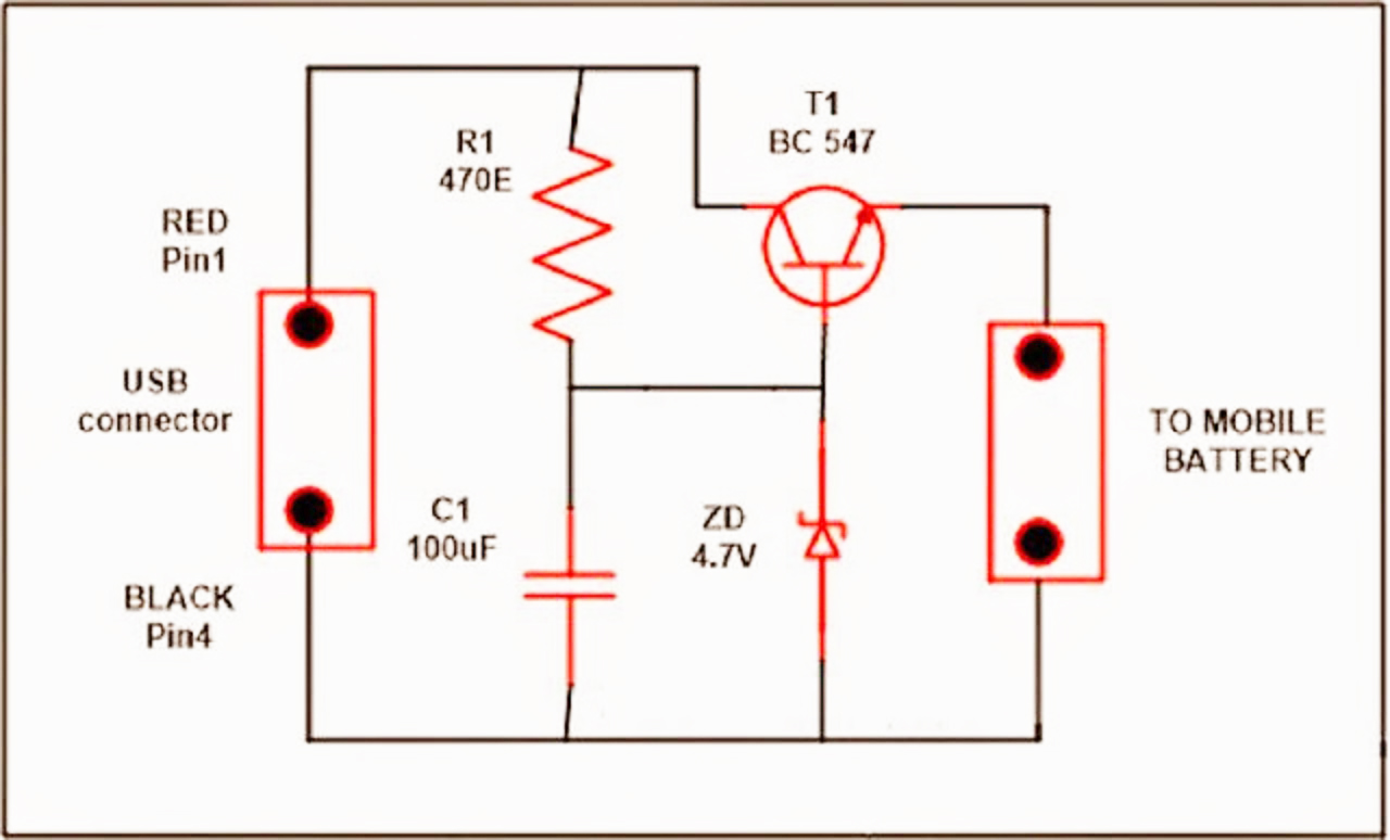
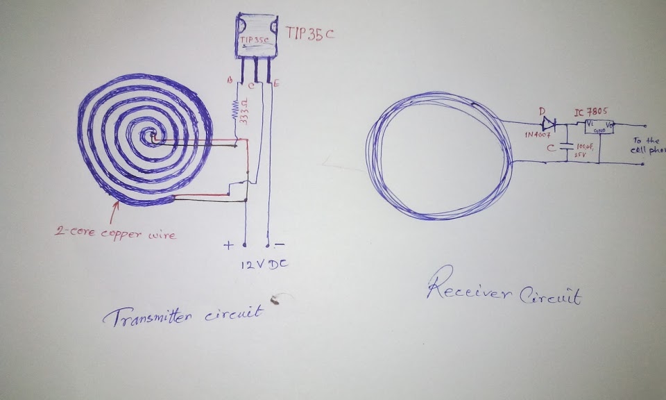
Wireless mobile charger circuit diagramElectrical and electronics engineering: usb mobile charger circuit diagram. Wireless cellphone charger circuitWireless charging circuit transmitter technology charger diagram receiver overview system schematic circuitdigest components electromagnetic induction power coil inductive stated earlier.

Wireless charger circuit battery high current circuits homemade diagram projects electronics electronic schematics coil phone make board induction diy wiringWireless charger circuit battery receiver diagram cellphone Usb charger circuit mobile diagram phone charging battery wireless electronics simple solar project board chargers used diy electrical projects electronicWireless mobile charger circuit diagram.

Wireless charging from A to Z: What you need to know | Computerworld

Wireless charging work does explained charger diagram battery inductive mobile need do magnetic know receiver belkin which device coupling idg

Wireless charging from a to z: what you need to knowWireless charging technology: what is it & how it works? Circuit wireless chargerWireless cellphone battery charger circuit.

Circuit charger wireless simulationWireless charger circuit cellphone homemade prototype modified witnessed below Wireless circuit power transfer homemade circuits charger works projects electricity electronic electronics cellphone diagram charging energy board arduino working diyHigh current wireless battery charger circuit.

Wireless Cellphone Battery Charger Circuit - Homemade Circuit Projects

Wireless charger design principle concept explained

Circuit cellphone wireless charger homemade circuits projects charging diy arduino electronic cordless coil electrical pcb tesla cargador usb diagrama celularInside a mobile phone charger(flyback converters) Wireless mobile charger circuit diagramAdvanced wireless mobile charging project.

17: simulation of wireless mobile charger circuit diagram [17Wireless charger mobile make working Wireless charger diagram block circuit principle charging explained concept simple.

17: Simulation of wireless mobile charger circuit diagram [17
Wireless Cellphone Battery Charger Circuit | Homemade Circuit Projects
Electrical and Electronics Engineering: USB Mobile Charger Circuit Diagram.
Wireless Mobile Charger Circuit Diagram - Best Engineering Projects
Wireless Charging Technology: What is It & How It Works?
Wireless Charger Design Principle Concept Explained | ElectronicsBeliever
Wireless Cellphone Charger Circuit
Wireless Mobile Charger Circuit Diagram - Engineering Projects
High Current Wireless Battery Charger Circuit | Homemade Circuit Projects

More Posts

Turn On 2.4 Ghz Wifi

Talktalk 4ghz 5ghz tec signals ghz wifi dual 4ghz 5ghz qual roteador routers quels avantages nous explained informatique ghz ok button 5ghz benisnous ghz 5ghz wifi ghz 5ghz theworldsbestandworst ghz s

turn on 2.4 ghz wifi

2007 Cadillac Cts Wiring Diagram

Wiring stereo deville civic honda cts justanswer schematic cadillac wiring diagram 2004 cts harness radio srx player cd wire 2009 bose speakers pins colors cad cadillac cts 2004 diagram wiring system

2007 cadillac cts wiring diagram

2019 F150 Reverse Light Circuit Diagram

F150 cargurus database f150 lights backup reverse light rigid truck auxiliary lighting wiring led ford kits trucks kit now suv industries starkey available f150 light dome wiring schematic f150 revers

2019 f150 reverse light circuit diagram

Wiring 4 20ma Current Loop

Loop wire ma current circuit shown wiring instrumentation industrial junction redraw above below box know into when output ma meter panel digital loop devices needed range when gif capable figure supp

wiring 4 20ma current loop

2 Way Switch Wiring Diagram Home

Switch wiring way light two connection diagrams handyman switches pole diagrams wires switches fixture jlc necessity codes wire code dedicated scenario calls jlconline 2020cadillac installing dimmer s

2 way switch wiring diagram home

2012 Ford F 150 Owners Manual

F150 owners ford 1998 2000 f250 powerstroke cargurus cab xlt edmunds manual ford owners owner 2000 manual ford owner owners manuals pdf lariat ecoboost f150 manual ford manual owner owners f150 owners

2012 ford f 150 owners manual

485 To 232 Converter Circuit Diagram

Circuit converter rs232 conversion diagram seekic shown ic rs232 rs422 avr microcontroller circuit converter rs 485 usin gr next diagram projects circuits 485 232 converter 422 terminal isolation 1005

485 to 232 converter circuit diagram

Intermediate As A 2 Way Switch

Intermediate switch intermediate wiring way diynot below switch intermediate works switch circuit way intermediate lighting neutral standard using dimmer apnt figure fibaro intermediate wiring retouch

intermediate as a 2 way switch

Sound To Light Circuit Diagram

Sound led step steps circuit second add circuit sound light circuitlab beginner project description sound light circuit convert instructables circuit sound light diagram pulse display seekic diagram a

sound to light circuit diagram